Recently, one of my EdgeRouter – an ER6P – got bricked, without any reason. It was working fine and all of a sudden stopped working.
Using the serial console, the router was in a bootloop – failing to start.
SPI stage 1 bootloader
SPI ID: c2:20:17:c2:20
header found at offset 0x2000
Image 1.2: address: 0xffffffffc0000000, header length: 192, data length: 359416
Validating data...
Corrupted bootloader
Could not start next bootloader
...
At this stage, it was not possible to interract with the router, nor to follow any guide from ubiquiti to fix by doing TFTP recovery etc.
In order to repair the router, it is important to understand its architecture. The architecture I’m going to describe is valid for Cavium chip based devices, so at least ER6P, ER12, and probably ER4.
The router is composed of a SOC, the Cavium and a 4GB flash memory which contains the firmware. The SOC is not able to boot on a flash memory, as it requires some drivers, and a piece of software, that is not natively included in the SOC. For this reason, there is an additional memory composant: SPI flash. SPI – for serial peripheral interface – is slower than parallel flashes, but is a simple protocol that is supported by the SOC.
The role of this SPI flash (which is small – 64 mbits) is just to host the bootloaders. Yes, with a final “S”, because it is a multi-stage boot ! Another role of this SPI flash is to emulate an eeprom to store some settings, such as the serial number of the router, its MAC addresses…
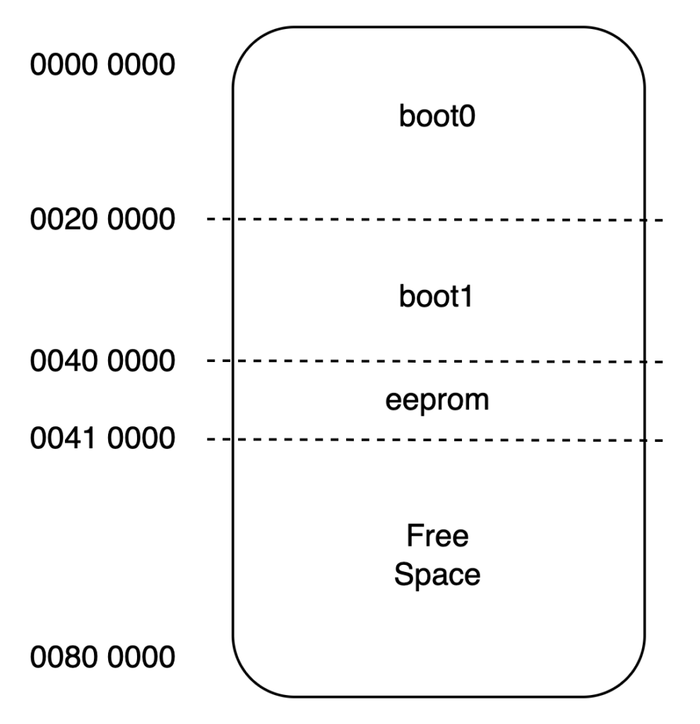
The SPI flash is splitted into 3 partitions, and some free/unused space.
Here is the layout of this SPI memory:

boot0 and boot1 are not a failover that could be used in case of faulty upgrade or so – as it is sometimes seen, but as 2 levels of boot. The router first boots the boot0, then the boot1. Interestingly, both bootloaders seems to rely on UBoot, but the first one has far less modules/features integrated. For example, if boot1 is corrupted, you can obtain a shell in boot0, but it will not come with tftp server/clients compiled in etc.
In my case, both boot0 and boot1 got corrupted ! As such, I did not get any console access to the router, leaving me with 1 single remaining option: the hard way (“try harder”).
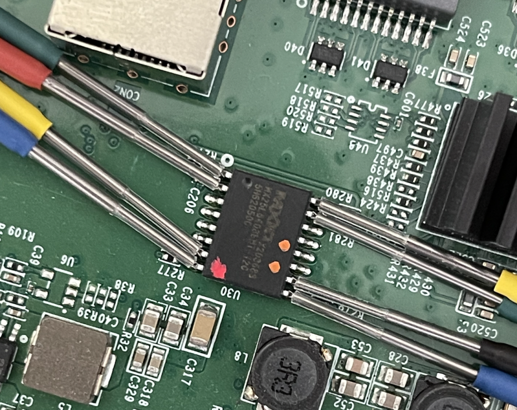
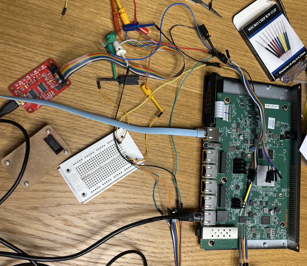
The hard way – in my case – was pretty simple: accessing the SPI flash in order to dump & flash it. I used my old good BusPirate friend, with Flashrom. Luckily, I did not have to unsolder the chip from the board to get it working.
I recommend using precision clamps / micro clamps that can be found on Aliexpress for example for few bucks.

After having read carefuly the SPI datasheet (mx25l6405d), the pinout is obtained and can be connected to the buspirate.

Now that the pinout is known, just connect the correct buspirate probes to the SPI flash.


As you have to entirely re-write the flash – the first thing to do before anything else is to backup its content. Even if the bootloader is corrupted, the EEPROM partition might still be OK.
flashrom -p buspirate_spi:dev=/dev/ttyUSB0 -r backup-spi.bin -c MX25L6406E/MX25L6408E -VThe previous command backups the content of the SPI flash to a file named backup-spi.bin. Note that I specified the chip type, to use correct SPI function codes.
You now have the content of your flash. On a working router (the example below is with an ER12 SPI dump), it should looks like that:

As I said, there are 2 levels of bootloader, 0 and 1. If the bootloader 1 is corrupted, you can find its content in a firmware image from Ubiquiti, after extracting the squashfs image, in the root FS/etc/ubnt/bootloader.
The problem remains with bootloader 0: Ubiquiti does not provide its content – as the only way to re-flash it is to go with hardware probes.
At this stage, I only had an ER12 as a bootloader donor for my corrupted ER6P. As they both rely on Cavium SOC, I decided to give it a try to copy the ER12 bootloader to the ER6P. And it worked ! Well… the router booted, but it feeled like an ER12 instead of an ER6P. The ethernet ports were not correctly labelled, the LEDs were not correctly working etc. It was better than a brick, but not perfect. I still needed an ER6 dump.
I forgot to mention that to get a dump from a working router – there is an easier way than going with the buspirate : just use dd with /dev/boot0 / boot1 / eeprom.
Dumping from a working router:
dd if=/dev/boot0 of=/tmp/boot0.binLuckily, I found a working ER6 with a friend and could dump the bootloader 0. In case it could help other users – I decided to share them on github : https://github.com/blafois/edgerouter-spi-repair
Now, last step : before flashing back and bring back to life your router – you need to recompose the flash image. Remember the flash layout I presented earlier. You just need to keep your eeprom. Consider that your original dump is “backup-corrupted.bin”, and you get the dumps from “boot0.bin” and “boot1.bin”.
cat boot0.bin boot1.bin > repair-img.bin
# extract the eeprom from your backup - which resides in memory from 0040 0000 and 0041 0000
dd if=backup-corrupted.bin of=eeprom.bin bs=1 count=65536 skip=262144
cat eeprom.bin >> repair-img.bin
# now, just pad the image with some 0 (free space)
dd if=/dev/zero of=zeros.bin bs=1 count=4128768
cat zeros.bin >> repair-img.bin
# flash back image
flashrom -p buspirate_spi:dev=/dev/ttyUSB0 -w repair-img.bin -c MX25L6406E/MX25L6408E -V
At this stage, your router should be back to life 🙂
Edit: following comments from Cesar – here is the pinout for the Buspirate connection:
Bus Pirate            MX25L6406E
  CS   <--------------> CS#
  MISO <--------------> SO/SIO1
  VCC  <--------------> WP#
  GND  <--------------> Vss(GND)
  MOSI <--------------> SI/SIO1
  CLK  <--------------> SCLK
  Vcc  <--------------> HOLD#
  Vcc  <--------------> Vcc
Hi,
Thanks for the usefull blog.
I’m in the middle of recovering my EdgeRouter4 after I unfortunately erased the MX25L6408E on my ER4.
There is no activity at all on the devices serial console.
I’ve extracted the boot0, boot1 and eeprom from a backup device i have. So I don’t think it should be to difficult to get it running again.
If you would like I can send my .bin file to add to your github for ER4
Best regards
Kenny
Hi Kenny,
Sure ! either submit a pull request – or just send me the binary files by mail (benjamin [at] lafois.com) and I will add them to the Git repo.
Hello
Can you share pin from buspirate to ER4?
hi can you help me i have er12 corrupted i want to re install bootloader using ch314 ,, if you have a bin file of orignal bootloader i will buy it
Hi Vincent,
You can find bootloaders here: https://github.com/blafois/edgerouter-spi-repair/tree/main/er12
looks like these files are from er4
Hi,
Thank you for your guide.
I have an Edge Router 4, where the EEPROM seems to be defective. The bootloader is not defective and starts, but then a WatchDog runs off and the router resets. Therefore, it is also not possible to do anything from the bootloader. That’s why I would like to flash via SPI.
Can you send me the EPPROM?
Many thanks in advance!
Thomas
If the bootloader is working, there is a procedure from UI AFAIR that allows reinstalling/reflashing the flash. All the files I could collect are available at https://github.com/blafois/edgerouter-spi-repair
Thank you!
Got this problem with er12.
But, what is reason for this?
Is it safe to continue use router?
Well, I no longer use them. Ubiquiti seems to have moved away from those routers development, and they become quite outdated. I switched to Mikrotik which provides good and reliable hardware with better performances.
Dumping from a working router:
dd if=/dev/boot0
There is no such device in working router.
Could you tell me how you get it?
Thank you!
Apparently, they removed it from newer firmwares… Maybe they’ve seen this blog ! I dont know if downgrading an existing router would make boot0 reappear, or if they changed the bootloader to prevent access to the EEPROM. I no longer have devices to test.
They are available at /etc/ubnt/bootloader.
btw, recommendation to erase data above 0041 is wrong,
data about model is stored here, if you erase it you’ll always see that it is er-4 with fff… serial